
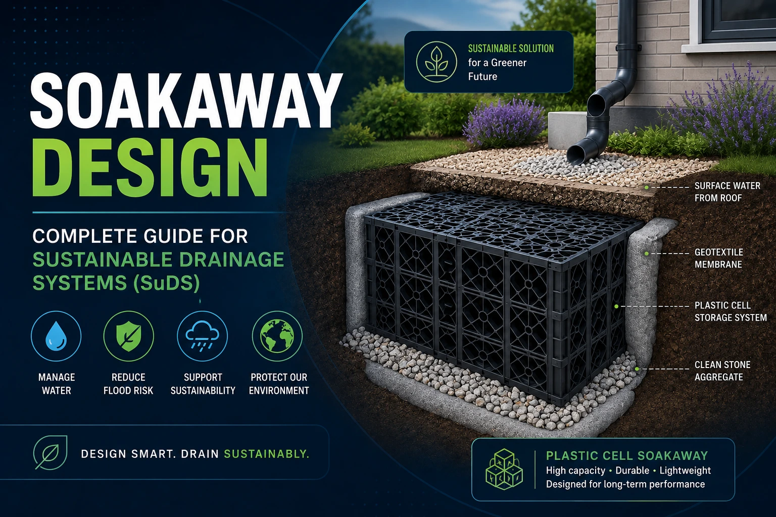
1. Introduction to Soakaway Design
Sustainable Drainage Systems (SuDS) represent a fundamental paradigm shift in modern stormwater engineering. Moving away from traditional rapid conveyance networks that quickly pipe surface water off-site, SuDS focuses on managing runoff at the source through attenuation, natural treatment, and infiltration. At the heart of this sustainable framework lies soakaway design—a core engineering discipline focused on safely discharging captured surface water into the receiving subsoil matrix.
1.1 Definition and Basic Mechanics of Soakaway Design
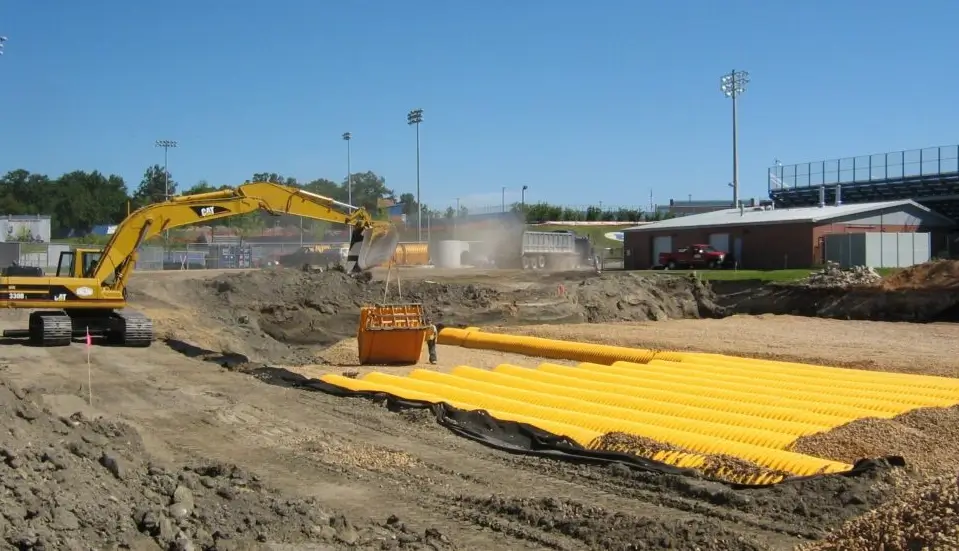
In modern soakaway design, a soakaway is defined as a subterranean infiltration structure engineered to collect, temporarily store, and gradually discharge surface water runoff into the surrounding ground. Modern soakaway design solutions range from traditional stone-filled excavations to high-efficiency modular geocellular crate systems and structural perforated concrete chambers.
The standard operation in soakaway design follows a simple flow pathway:
- Inflow & Capture: Surface water runoff enters via gravity pipework.
- Pre-Treatment: Water passes through a silt trap or interceptor to remove sediments.
- Volumetric Storage: Runoff fills the void space provided by the soakaway design structure.
- Infiltration: Water percolates radially and vertically into surrounding unsaturated subsoil layers.
1.2 Purpose and Strategic Role of Soakaway Design in SuDS
In sustainable drainage frameworks, proper soakaway design acts as a primary source control mechanism. Technical objectives of soakaway design include:
- Replicating natural pre-development hydrological regimes by encouraging localized infiltration.
- Recharging deep and shallow groundwater aquifers within the local river basin catchment.
- Attenuating peak stormwater flows to prevent downstream sewer surcharging and fluvial flooding.
- Providing natural physical and biological attenuation as runoff filters through surrounding soil strata.
1.3 Advantages of Soakaway Design vs. Traditional Piped Drainage
- Peak Flow Attenuation: Effective soakaway design eliminates direct high-velocity discharge into watercourses, mitigating downstream erosion and flood risks.
- Aquifer Recharge: Direct groundwater replenishment maintains local baseflows during dry spells.
- Infrastructure Cost Savings: Optimized soakaway design substantially reduces pipe network diameters, excavation depths, and downstream pumping stations.
- Water Quality Improvement: Soil filtration traps heavy metals, micro-pollutants, and suspended solids.
1.4 Applications of Soakaway Design Across Project Sectors
- Residential: Roof water disposal for individual dwellings, housing developments, and driveway attenuation.
- Commercial & Industrial: High-roof logistics centers, retail developments, and commercial parking areas.
- Infrastructure & Highways: Highway runoff management using linear infiltration trenches and verge schemes.
1.5 Technical Limitations and Constraints in Soakaway Design
Despite its benefits, soakaway design is not universally applicable. Key constraints in soakaway design include:
- Infiltration failure occurs in low-permeability soils such as heavy clays and silts (where measured infiltration rates drop below 1 x 10⁻⁶ m/s).
- A minimum separation distance of 1.0 m is required between the soakaway base and the seasonal high groundwater table.
- Prohibited in contaminated ground where infiltration would mobilize subsurface pollutants into potable aquifers.
- Unsuitable in geotechnically unstable ground, such as soluble chalk, landslide zones, or expansive clay foundations.
2. Soakaway Design Principles and Hydraulic Behaviour
The hydraulic behavior in soakaway design is governed by the dynamic interaction between storm runoff inflow, temporary internal void storage, and soil infiltration capacity.
2.1 Fundamental Hydraulic Mechanics in Soakaway Design
When analyzing soakaway design under storm conditions, runoff enters the soakaway at a rate Qin(t), which varies according to the site rainfall hydrograph. Infiltration into the surrounding soil occurs simultaneously at a rate Qout(t), governed by Darcy’s Law and the hydraulic head within the tank. The difference between inflow and outflow accumulates as temporary storage volume Vstorage within the void space.
Vinflow = Vstorage + Vinfiltration + Voverflow
Where:
- Vinflow = Integral of Qin(t) dt over storm duration t (m³)
- Vstorage = Maximum effective fluid storage volume required by the soakaway design (m³)
- Vinfiltration = Integral of Qout(t) dt over storm duration t (m³)
- Voverflow = Exceedance volume (m³), which must equal ZERO for the design return period.
2.2 Key Hydraulic Factors in Soakaway Design
- Surface Runoff Inflow: Directly functions as a parameter of rainfall intensity (i), effective catchment area (Ae), and runoff coefficient (C).
- Internal Storage Capacity: The physical volume provided within the soakaway design matrix.
- Infiltration Outflow Rate: Governed by the soil hydraulic conductivity (f), hydraulic gradient, and effective wetted surface area.
- Seasonal Groundwater Interaction: High water tables reduce effective hydraulic head, limit vertical infiltration, and compromise the soakaway design.
2.3 Emptying Time Requirement (t50) in Soakaway Design
A critical requirement in standard soakaway design (BRE Digest 365 and CIRIA C753) is that the soakaway must drain to 50% of its maximum storage volume within 24 hours (t50 ≤ 24 hours). This safety criterion ensures that the soakaway design recovers sufficient volumetric capacity to accommodate subsequent storm events occurring in close succession.
3. Types of Soakaway Design Configurations
Selecting the appropriate soakaway design type depends on structural loading conditions, spatial constraints, available footprint, budget, and long-term maintenance requirements.
| Soakaway Design Type | Void Ratio | Footprint | Load Capacity | Capital Cost | Typical Applications |
|---|---|---|---|---|---|
| Traditional Stone-Filled | 30% – 35% | Large | Moderate to High | Low Material Cost | Domestic roofs, low-density housing |
| Geocellular Crates | 95% – 96% | Minimal | Low to High (Specified) | Medium | Commercial sites, parking, urban roofs |
| Concrete Chamber | > 90% (Internal) | Small / Deep | Very High (SLW 30 / HGV) | High | High-load highways, deep permeable strata |
| Infiltration Trench | 30% – 35% | Linear Edge | Moderate | Low to Medium | Highway verges, site boundaries, long slopes |
3.1 Traditional Stone-Filled Soakaway Design
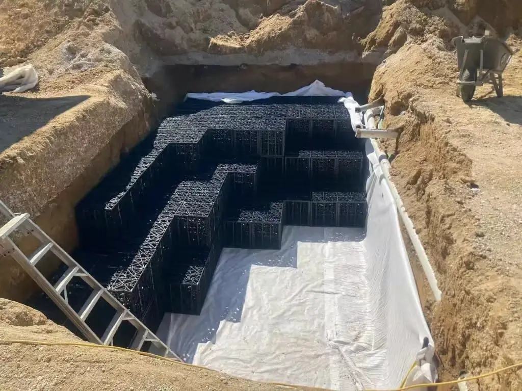
This soakaway design features an excavation filled with clean single-sized aggregate wrapped in geotextile. Provides a void ratio of 30% to 35% (n = 0.30 – 0.35). Simple and low-cost for small roof areas, but requires a large physical footprint.
3.2 Geocellular Modular Crate Matrix Soakaway Design
Engineered modular crates assembled into a subterranean block matrix. This soakaway design features an extremely high void ratio of 95% to 96% (n = 0.95 – 0.96), which minimizes excavation volume and spatial footprint.
3.3 Concrete Chamber / Ring Soakaway Design
Precast perforated concrete manhole rings or chambers installed on gravel backfill. This soakaway design is excellent for high traffic wheel loading and provides direct physical access for silt inspection, suction clearing, and high-pressure jetting.
3.4 Linear Infiltration Trench Soakaway Design
A continuous aggregate- or crate-filled trench containing a central perforated distribution pipe. This soakaway design distributes infiltration along highway verges or linear boundaries.
4. Site Investigation Requirements for Soakaway Design
Comprehensive ground investigation is mandatory prior to completing any professional soakaway design calculations.
4.1 Soil Investigation & BRE Digest 365 Testing for Soakaway Design
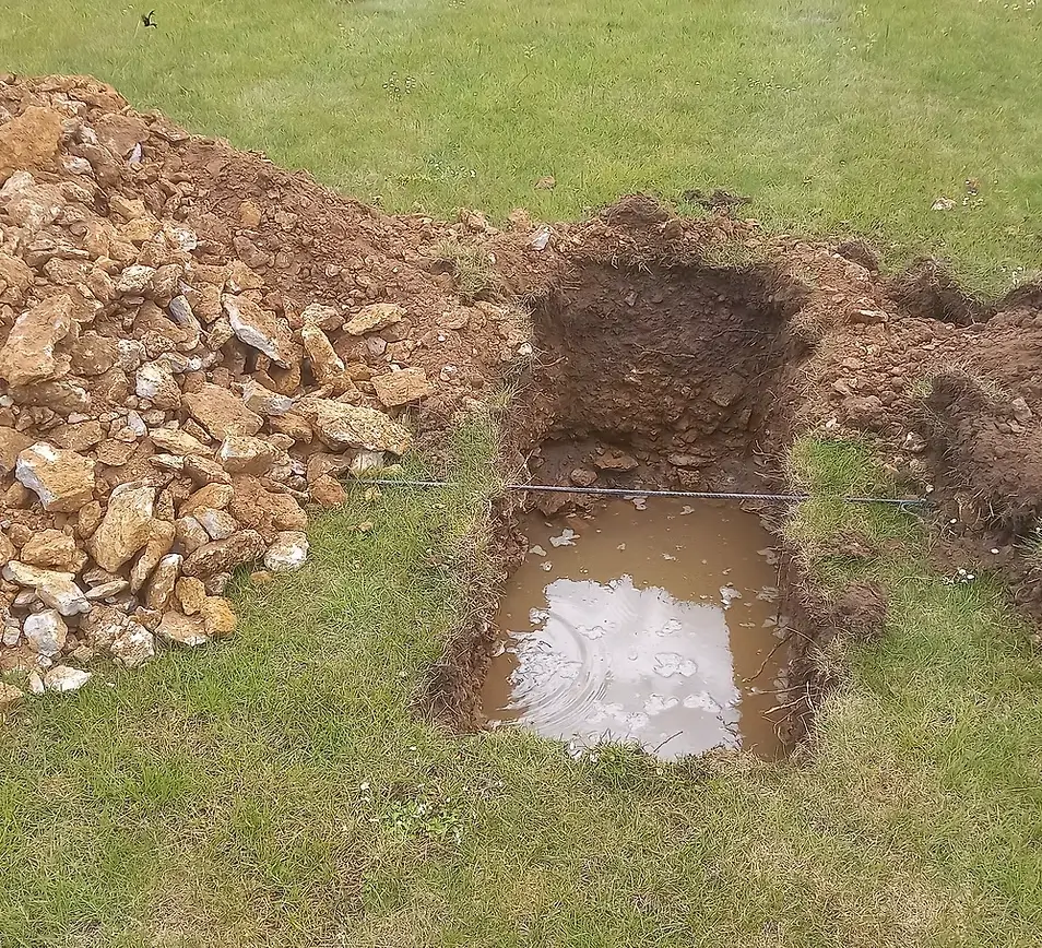
Soil suitability for soakaway design must be verified through trial pit excavations and field percolation testing in accordance with BRE Digest 365. Trial pits are excavated to the depth of the proposed soakaway base to calculate the design soil infiltration rate (f).
4.2 Groundwater Table Assessment in Soakaway Design
In robust soakaway design, the base of the structure must remain at least 1.0 metre above the maximum anticipated seasonal high groundwater table to prevent structural flooding and contamination risks.
4.3 Setback Distances and Site Constraints in Soakaway Design
- Building Foundations: Minimum 5.0 metres clearance from footings in standard soakaway design (10.0 m in expansive clays).
- Slopes & Embankments: Minimum 5.0 metres setback from retaining walls or slope crests.
- Boundaries & Utilities: Minimum 2.5 to 5.0 metres from site boundaries and underground services.
5. Soakaway Design Methodology (Main Section)
The standard engineering procedure for soakaway design consists of a rigorous 5-step workflow.
Step 1: Determine Effective Catchment Area for Soakaway Design
Calculate the total impermeable plan area contributing runoff to the soakaway, multiplied by the appropriate surface runoff coefficient (C):
Ae = Σ(Ai × Ci) | Peak Flow Q = C × i × A
Standard Runoff Coefficients (C):
- Pitched Slate / Tile Roofs: 0.90 – 0.95
- Flat Membrane Roofs: 0.85 – 0.90
- Asphalt & Concrete Pavements: 0.90 – 0.95
- Permeable Paving with Sub-base Infiltration: 0.00 – 0.10
Step 2: Determine Design Rainfall Parameters for Soakaway Design
Select the design return period based on regulatory requirements. Apply climate change uplift factors (+20% to +40%) to peak rainfall intensities during the soakaway design process. Evaluate multiple storm durations (15 minutes to 24 hours) to identify the critical duration.
Step 3: Calculate Required Storage Volume in Soakaway Design
Calculate the net volumetric difference between cumulative rainfall inflow and simultaneous soil infiltration outflow over the storm duration:
Net Storage Equation: Vstorage = Vinflow – Vinfiltration
Step 4: Determine Design Infiltration Rate for Soakaway Design
Apply a Factor of Safety (Fs) to the raw field-measured infiltration rate (fmeasured) in your soakaway design:
fdesign = fmeasured / Fs
Recommended Safety Factors (Fs) in Soakaway Design:
- Small Domestic Sites (< 100 m² catchment): Fs = 1.5
- Residential / Commercial Sites (100 m² – 1,000 m² catchment): Fs = 2.0
- Major Infrastructure / Sensitive Catchments (> 1,000 m² catchment): Fs = 3.0 to 10.0
Step 5: Calculate Physical Dimensions in Soakaway Design
Determine physical gross excavation dimensions (Length L × Width W × Depth d) required by the soakaway design using the internal void ratio (n):
Gross Volume Required: Vgross = Vstorage / n
- Stone-Filled Soakaway Design: Vstorage = L × W × d × 0.35
- Geocellular Crate Soakaway Design: Vstorage = L × W × d × 0.95
6. BRE Digest 365 Soakaway Design Method
BRE Digest 365 specifies the standard UK methodology for soakaway design. The philosophy balances inflow volume against outflow volume during critical storm durations while satisfying the half-emptying time limit.
Inflow Volume: I = Ae × R
Outflow Volume: O = as50 × fdesign × D
Required Storage: S = I – O
Where:
- Ae = Effective catchment area (m²)
- R = Total design rainfall depth for duration D (m)
- as50 = Internal surface area at 50% storage depth in the soakaway design (m²)
- fdesign = Design soil infiltration rate (m/s)
- D = Storm event duration (seconds)
- as50 formula: as50 = (L + W) × d (excluding base due to siltation risks)
7. Detailed Worked Soakaway Design Example
The following complete calculation demonstrates the step-by-step engineering procedure for a residential roof soakaway design.
- Project Type: Residential Apartment Complex Roof Drainage
- Catchment Plan Area (A): 1,000 m² (Pitched slate roof, C = 0.90)
- Effective Catchment Area (Ae): 1,000 × 0.90 = 900 m²
- Design Return Period: 1-in-100-year storm + 40% Climate Change uplift
- Critical Storm Event Depth (R): 50 mm = 0.050 m (2-hour duration event)
- Storm Duration (D): 2 hours = 7,200 seconds
- Measured Soil Infiltration Rate (fmeasured): 1.0 × 10⁻⁵ m/s (36 mm/hr)
- Design Factor of Safety (Fs): 1.5
- Proposed Structure: HDPE Geocellular Crates (Void ratio n = 0.95)
- Target Dimensions: Fixed depth d = 1.6 m, Length L = 6.0 m, Width W = 5.0 m
Step-by-Step Calculation Solution:
Step 1: Inflow Volume Calculation (I)
I = Ae × R = 900 m² × 0.050 m = 45.00 m³
Step 2: Design Infiltration Rate Calculation (fdesign)
fdesign = fmeasured / Fs = (1.0 × 10⁻⁵ m/s) / 1.5 = 6.67 × 10⁻⁶ m/s
Step 3: Internal Surface Area at 50% Storage Depth (as50)
as50 = (L × W) + (L + W) × d [Including base area]
as50 = (6.0 × 5.0) + (6.0 + 5.0) × 1.6 = 30.0 + 17.6 = 47.60 m²
Step 4: Outflow Volume During Storm (O)
O = as50 × fdesign × D = 47.60 m² × (6.67 × 10-6 m/s) × 7,200 s = 2.29 m³
Step 5: Net Required Storage Volume (Sreq)
Sreq = I – O = 45.00 m³ – 2.29 m³ = 42.71 m³
Step 6: Storage Volume Provided by Proposed Tank (Sprovided)
Sprovided = L × W × d × n = 6.0 m × 5.0 m × 1.6 m × 0.95 = 45.60 m³
Volumetric Check: Sprovided (45.60 m³) ≥ Sreq (42.71 m³) → ADEQUATE & COMPLIANT
Step 7: Half-Emptying Time Verification (t50)
Half Required Storage V50 = 42.71 m³ / 2 = 21.355 m³
t50 = V50 / (as50 × fdesign) = 21.355 m³ / (47.60 m² × 6.67 × 10-6 m/s)
t50 = 21.355 / (3.175 × 10⁻⁴ m³/s) = 67,260 seconds = 18.68 hours
Drain-Down Check: t50 (18.68 hours) ≤ 24.0 hours → COMPLIANT WITH BRE DIGEST 365
8. Critical Soakaway Design Considerations
A successful soakaway design installation requires careful attention to structural integrity, environmental safety, and long-term maintainability.
8.1 Structural Loading Categories in Soakaway Design
- Landscaping / Non-Trafficked Areas: Minimum cover depth = 0.5 m; vertical crate compressive strength ≥ 200 kN/m².
- Car Parks / Light Traffic Areas: Minimum cover depth = 1.0 to 1.2 m; vertical crate compressive strength ≥ 400 – 500 kN/m².
- Heavy Commercial / Highway Areas: Requires structural soakaway design assessment of lateral Earth pressures and heavy axle load dispersion (Eurocode 1 BS EN 1991-2).
8.2 Maintenance and Pre-Treatment in Soakaway Design
- Silt Catchpits: Mandatory in soakaway design to trap sediments upstream via a minimum 300 mm deep sump.
- Oil Separators: Essential for commercial parking lots to intercept hydrocarbons prior to infiltration.
- Geotextile Envelope: High-flow needle-punched geotextile must surround the matrix in all soakaway design schemes.
9. Common Soakaway Design Errors and Solutions
| Common Soakaway Design Error | Technical Impact | Engineering Solution |
|---|---|---|
| Ignoring High Water Table | Loss of volume, flotation failure, water table pollution | Perform winter groundwater monitoring; ensure ≥ 1.0m base clearance. |
| Omitting Safety Factor | Under-sizing, surface ponding, premature failure | Apply BRE Digest 365 safety factors (Fs = 1.5 to 10) to raw test rates. |
| No Upstream Silt Interceptor | Silt clogs voids, severe drop in infiltration rate | Install catchpits with sumps or pre-treatment swales/bioretention. |
| Installing in Unsuitable Clay | Complete standing water, failure to empty within 24h | Conduct BRE 365 field tests; use attenuation basins for low-k soils. |
| Encroaching on Foundations (<5m) | Structural settlement, foundation instability, basement leaks | Enforce strict 5.0m minimum setback distance from all footings. |
10. Soakaway Design Modelling in Hydraulic Software
Modern hydraulic engineering relies on specialized software suites to model and validate soakaway design within broader drainage networks.
10.1 Autodesk InfoWorks ICM & InfoDrainage
Modeled as a Storage Node or Infiltration Tank. Parameters in soakaway design include storage depth-area curves, matrix porosity, infiltration surface areas, and soil hydraulic conductivity.
10.2 US EPA SWMM (Storm Water Management Model)
Represented using Storage Units with exfiltration links or through LID Control blocks to verify the hydraulic performance of the soakaway design.
10.3 Causeway MicroDrainage
Modeled as an Infiltration Tank or Storage Structure. Inputs include L × W × d dimensions, aggregate/crate porosity percentage, BRE 365 safety factors, and automated verification of 24-hour half-emptying compliance for your soakaway design.
11. Sustainable Benefits of Effective Soakaway Design
- Flood Risk Mitigation: Diverts surface water from sewer networks, directly lowering peak flood risks.
- Groundwater Recharge: Replenishes shallow and deep aquifers, sustaining river baseflows during dry summers.
- Piped Network Reduction: Efficient soakaway design eliminates the need for large-diameter downstream attenuation pipes.
- Water Quality Enhancement: Natural soil percolation traps pollutants, micro-plastics, and trace metals.
- Climate Resilience: Sustainable soakaway design adapts urban sites to higher rainfall intensities driven by climate change.
12. Soakaway Design Standards and References
- BRE Digest 365: Soakaway Design (Building Research Establishment publication).
- CIRIA C753 (2015): The SuDS Manual (Comprehensive UK framework for SuDS planning and engineering).
- BS EN 752: Drainage and Sewer Systems Outside Buildings.
- Building Regulations Approved Document H (Section H3): Rainwater Drainage (UK statutory compliance standards).
- ASCE/EWRI 45-12: Standard Guidelines for the Design of Urban Stormwater Systems.
13. Frequently Asked Questions (FAQ) on Soakaway Design
Q1: What is the minimum acceptable soil infiltration rate for soakaway design?
A: The standard minimum infiltration rate in soakaway design is 1.0 × 10⁻⁶ m/s (3.6 mm/hr). Infiltration rates below this threshold result in unfeasibly large storage volumes and fail the 24-hour half-emptying criterion.
Q2: Why is the 24-hour half-emptying requirement (t50) critical in soakaway design?
A: The t50 rule ensures the soakaway design rapidly recovers at least 50% of its storage capacity within one day, preventing system failure if consecutive storm events occur in quick succession.
Q3: Can a soakaway design be implemented in clay soil?
A: Generally, no. Heavy clay soils have permeability rates between 10-8 m/s and 10-10 m/s, which are too low for functional soakaway design. In clay soils, attenuation basins or bioretention cells with controlled surface discharge must be used.
Q4: What happens if a soakaway design places the tank closer than 5 metres to a building?
A: Saturation of subsoils near building footings can lead to loss of soil bearing capacity, differential foundation settlement, structural cracking, basement flooding, or slope instability.
14. Technical Conclusion on Soakaway Design
Professional soakaway design sits at the intersection of hydraulic engineering, geotechnical analysis, and sustainable urban development. By applying rigorous hydro-geological principles—such as BRE Digest 365 calculations, comprehensive soil testing, structural load evaluation, and safety factors—engineers can deliver durable soakaway design solutions that reduce urban flood risks, recharge vital aquifers, and safeguard civil infrastructure for decades to come.

 Inar Learn