Hydraulic Engineering Tools
Bernoulli Equation Calculator
Solve pressure head, velocity head, elevation head, pump head, and head losses with interactive charts, engineering diagrams, and printable reports. Built for civil, mechanical, and environmental engineers.
Bernoulli's Equation
The principle of conservation of energy applied to flowing fluids — the foundation of hydraulic engineering.
Smart Bernoulli Calculator
Select a calculation mode — the target parameter will be highlighted and its input field disabled. All other values are used to solve for it.
Input Parameters
Live editingResults Dashboard
8 key metricsPower & Cavitation Analysis
Calculation History
0 savedStep-by-Step Calculation
Animated Engineering Diagrams
Watch fluid flow in real-time with animated pipe flow visualization and dynamic energy distribution.
🌊 Animated Pipe Flow System
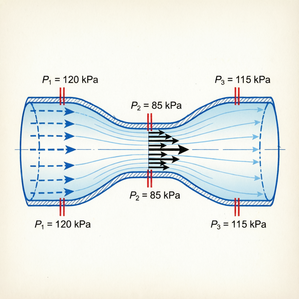
📐 Venturi Tube — Bernoulli Principle
Interactive Engineering Charts
Visualize energy distribution, hydraulic grade lines, and sensitivity analysis in real time.
Energy Head Distribution
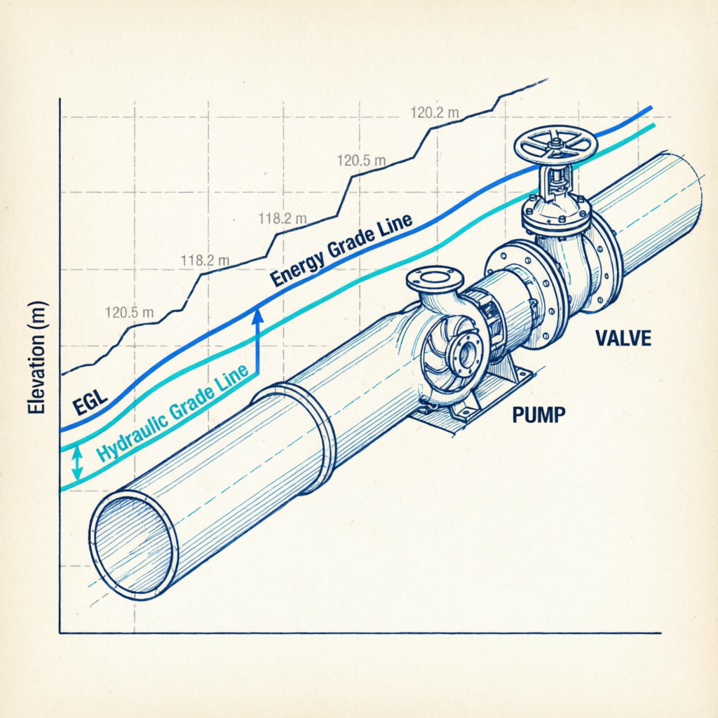
HGL & EGL Profile
Sensitivity Analysis
Velocity vs Pressure (Bernoulli Principle)
Interactive Moody Chart
Find the Darcy friction factor based on Reynolds number and relative roughness.
📉 Moody Diagram
Hydraulic Diagrams
Visual reference diagrams for common Bernoulli applications in fluid mechanics.
🔬 Venturi Tube — Pressure Variation
📐 Energy Grade Line & Hydraulic Grade Line
Engineering Tables
Quick reference tables for head components, fluid properties, Reynolds classification, minor loss coefficients, and unit conversions.
Head Components
| Parameter | Symbol | Equation | Unit |
|---|---|---|---|
| Pressure Head | hₚ | P / γ | m (ft) |
| Velocity Head | hᵥ | V² / 2g | m (ft) |
| Elevation Head | z | z | m (ft) |
| Total Head | H | P/γ + V²/2g + z | m (ft) |
| Pump Head | Hₚ | Energy added by pump | m (ft) |
| Turbine Head | Hₜ | Energy extracted by turbine | m (ft) |
| Major Head Loss | h_f | f(L/D)(V²/2g) | m (ft) |
| Minor Head Loss | h_m | ΣK(V²/2g) | m (ft) |
Fluid Properties at 20°C
| Fluid | Density ρ (kg/m³) | Specific Weight γ (N/m³) | Dynamic Viscosity μ (Pa·s) | Vapor Pressure (kPa) |
|---|---|---|---|---|
| Water | 998 | 9,790 | 1.002 × 10⁻³ | 2.34 |
| Seawater | 1,025 | 10,050 | 1.08 × 10⁻³ | 2.30 |
| Wastewater | 1,000 | 9,810 | 1.10 × 10⁻³ | 2.34 |
| Oil (SAE 30) | 917 | 8,990 | 0.29 | 0.01 |
| Gasoline | 680 | 6,670 | 2.9 × 10⁻⁴ | 55.0 |
| Mercury | 13,546 | 132,900 | 1.56 × 10⁻³ | 0.16 |
| Air | 1.204 | 11.8 | 1.82 × 10⁻⁵ | — |
Reynolds Number Classification
| Flow Regime | Reynolds Number (Pipe) | Characteristics |
|---|---|---|
| Laminar | Re < 2,300 | Smooth, orderly parallel flow layers |
| Transitional | 2,300 ≤ Re ≤ 4,000 | Unstable, intermittent turbulence |
| Turbulent | Re > 4,000 | Chaotic, mixed flow with eddies |
Minor Loss Coefficients (K factors)
| Fitting | K Value | Notes |
|---|---|---|
| Gate Valve (open) | 0.15 | Fully open |
| Globe Valve (open) | 10.0 | Fully open |
| Ball Valve (open) | 0.05 | Fully open |
| 90° Elbow (standard) | 0.9 | Long radius |
| 45° Elbow | 0.4 | Standard |
| Tee (straight) | 0.6 | Flow through run |
| Tee (branch) | 1.8 | Flow through branch |
| Check Valve | 2.5 | Swing type |
| Sharp entrance | 0.5 | Re-entrant |
| Sharp exit | 1.0 | Exit to reservoir |
Unit Conversions
| Quantity | SI Unit | Imperial Unit | Conversion Factor |
|---|---|---|---|
| Pressure | Pa, kPa, bar | psi | 1 psi = 6.895 kPa |
| Velocity | m/s | ft/s | 1 m/s = 3.281 ft/s |
| Length | m | ft | 1 m = 3.281 ft |
| Flow Rate | m³/s, L/s | ft³/s (cfs) | 1 m³/s = 35.315 cfs |
| Density | kg/m³ | lb/ft³ | 1 kg/m³ = 0.0624 lb/ft³ |
| Power | kW | hp | 1 kW = 1.341 hp |
Engineering Applications
Bernoulli's Equation is applied across every branch of hydraulic and fluid engineering.
Water Supply Networks
Design pressure zones and pipe sizing for municipal water distribution systems.
Sewer Systems
Analyze gravity flow and surcharge conditions in storm and sanitary sewers.
Pumping Stations
Calculate required pump head, NPSH, and system curves for pump selection.
Irrigation Systems
Design sprinkler and drip irrigation networks with uniform pressure distribution.
Hydropower Systems
Estimate turbine head and power output from reservoir elevation differences.
HVAC Systems
Analyze air flow in ducts, fan pressure requirements, and venturi effects.
Pipeline Design
Size oil and gas pipelines, calculate pressure drops and pump spacing.
Firefighting Systems
Design fire hydrant networks and sprinkler systems with adequate pressure.
Venturi & Orifice Meters
Measure flow rates using pressure differential across constrictions.
Hydraulic Structures
Analyze flow over weirs, through gates, and in open channels.
Process Engineering
Design chemical process piping, heat exchangers, and reactor feed systems.
Aerodynamics
Explain lift generation on airfoils and pressure distribution on bodies.
Help & Frequently Asked Questions
Everything you need to understand and correctly apply Bernoulli's Equation in engineering practice.
What is Bernoulli's Equation?
Bernoulli's Equation is a statement of the conservation of energy principle applied to flowing fluids. Derived by Daniel Bernoulli in 1738, it states that for steady, incompressible, inviscid flow along a streamline, the sum of pressure head, velocity head, and elevation head remains constant.
Assumptions & Limitations
- Steady flow: Velocity and pressure do not change with time at any point.
- Incompressible fluid: Density is constant (valid for liquids and low-speed gases, Ma < 0.3).
- Inviscid flow: No friction losses (real flows require the hₗ loss term).
- Along a streamline: Equation applies between two points on the same streamline.
- No energy addition/extraction: Pumps and turbines must be explicitly modeled with Hₚ and Hₜ terms.
Frequently Asked Questions
The Hydraulic Grade Line (HGL) represents P/γ + z — the height to which water would rise in a piezometer tube. The Energy Grade Line (EGL) represents P/γ + V²/2g + z — the total mechanical energy per unit weight. The vertical distance between EGL and HGL equals the velocity head V²/2g.
NPSH (Net Positive Suction Head) is the difference between the pump inlet pressure and the fluid's vapor pressure. NPSH Available (NPSHa) must exceed NPSH Required (NPSHr) by the pump manufacturer to prevent cavitation.
Bernoulli's Equation fails for compressible flows at high Mach numbers (Ma > 0.3), highly viscous flows, unsteady/transient flows, flows with significant heat transfer, and across shocks or sudden expansions without loss terms.
Use the extended Bernoulli equation with the head loss term hₗ = h_f + h_m. Major losses: h_f = f(L/D)(V²/2g) using Darcy-Weisbach. Minor losses: h_m = ΣK(V²/2g) where K is the loss coefficient for each fitting.
The Moody chart is a log-log plot of friction factor f vs Reynolds number Re for various relative roughness values ε/D. For laminar flow (Re < 2300), f = 64/Re regardless of roughness. For turbulent flow, use the Colebrook equation or Moody chart.
Pump power (shaft power) = γ × Q × Hₚ / ηₚ, where γ is specific weight (N/m³), Q is flow rate (m³/s), Hₚ is pump head (m), and ηₚ is pump efficiency (decimal). The result is in Watts. For kW, divide by 1000.
Yes, for low-speed gas flows (Mach number < 0.3) where density changes are less than about 5%. For high-speed compressible flows, use the compressible form of Bernoulli's equation or isentropic flow relations.
Cavitation occurs when local pressure drops below the vapor pressure of the fluid, causing vapor bubbles to form and collapse. Bernoulli's equation predicts pressure drops at high-velocity regions (constrictions). This is critical in pump design (NPSH analysis).
References & Standards
- White, F. M. (2011). Fluid Mechanics, 7th Edition. McGraw-Hill Education.
- Çengel, Y. A. & Cimbala, J. M. (2013). Fluid Mechanics: Fundamentals and Applications, 3rd Edition. McGraw-Hill.
- Chow, V. T. (1959). Open-Channel Hydraulics. McGraw-Hill.
- Munson, B. R., Young, D. F., Okiishi, T. H. (2013). Fundamentals of Fluid Mechanics, 7th Edition. Wiley.
- ASCE Manuals and Reports on Engineering Practice No. 37 — Design of Urban Stormwater Systems.
- Hydraulic Institute Standards (HI) — Rotodynamic Pumps for Nomenclature and Definitions.
- Engineering Toolbox — Fluid Mechanics Reference Data and Equations.
- AWWA M11 — Steel Pipe: A Guide for Design and Installation.
- Crane Co. (2009). Flow of Fluids Through Valves, Fittings, and Pipe. Technical Paper 410.
 Inar Learn