
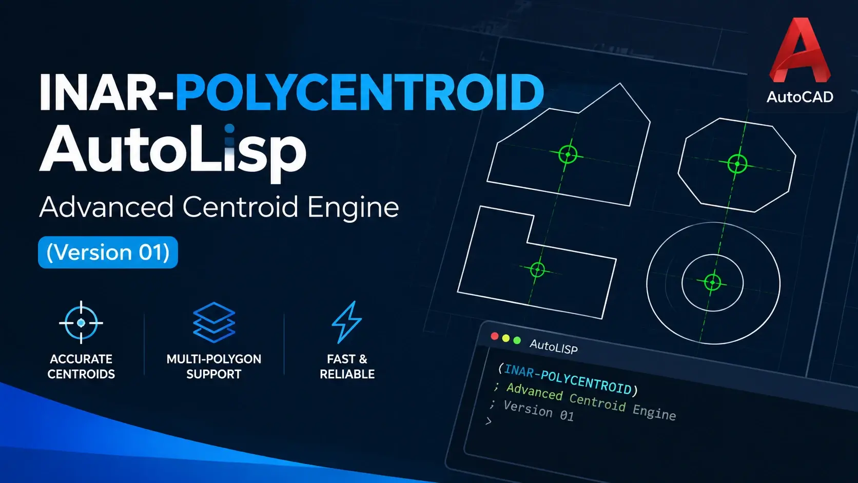
Finding the centroid of a polygon is easy for one rectangle and tedious for two hundred irregular parcels, zones, or plots. INAR-POLYCENTROID is an AutoLISP routine that takes a selection of closed polylines and text, calculates each polygon’s centroid and area, drops a marker at that location, and delivers the results as an AutoCAD table and an optional Excel sheet, all from a single dashboard.
This help page explains what a LISP routine is, why using one is worthwhile, what INAR-POLYCENTROID can and cannot do, and exactly how to install and run it, step by step.
Load the file with APPLOAD, type INAR-POLYCENTROID, select your closed polylines (and any text inside them), choose your options in the dashboard, and click OK. You get centroid markers, an ID and layer for each polygon, and a ready-made data table.
Introduction to INAR-POLYCENTROID
INAR-POLYCENTROID is a single-file AutoLISP command (INAR-POLYCENTROID_V01.lsp) that turns a repetitive survey and drafting job into a one-click workflow. It was written for engineers, surveyors, planners, and CAD technicians who regularly need to label, locate, and tabulate polygons.
What it does in one pass
What you get for every polygon
- A centroid marker as an AutoCAD Point, an AutoCAD Circle, or a Civil 3D COGO point.
- The centroid Easting (X), Northing (Y), and optional Elevation (Z).
- The polygon area, in your drawing units.
- An automatic Polygon ID such as
PLY-001, with a prefix you choose. - A layer assignment, either taken from the text inside the polygon or from a custom layer name.
Anyone working with closed boundaries in AutoCAD: land parcels, building footprints, catchment areas, lots, rooms, zones, or tank outlines. If you have ever used MASSPROP or AREA on many objects one by one, this routine replaces that loop.
What Is a LISP Routine?
AutoLISP is the scripting language built directly into AutoCAD. A LISP routine is a plain-text file with the .lsp extension that defines one or more custom commands. Once it is loaded, those commands behave exactly like the built-in ones: you type the name, answer the prompts, and the work is done.
What makes LISP unusually powerful for CAD is that it lives inside the application. It can read every entity in the drawing, calculate geometry, create new objects, alter layers, build tables, and — through Visual LISP’s COM bridge — even talk to Civil 3D and Microsoft Excel. No compiler, no SDK, no installer.
INAR-POLYCENTROID is a single such file. Everything it does — geometry analysis, dashboard dialog, layer creation, table drafting, Excel export — is contained in one text file you can read, edit, and share.
Anatomy of the routine
The File
A plain-text .lsp file. Open it in Notepad, VS Code, or any editor. Version-control it like source code.
The Command
Any function prefixed with c: becomes a typed command. Here it is INAR-POLYCENTROID.
The Dialog
A DCL dashboard is generated at runtime, so options are set with checkboxes and dropdowns — not typed prompts.
The COM Bridge
Visual LISP reaches AutoCAD tables, Civil 3D points, and Excel through COM automation — all from the same file.
Why Is It Important to Use LISPs?
Every CAD office has repetitive work: the same labels, the same tables, the same clean-up on every drawing. LISP is the lowest-cost way to automate it, because it ships inside the software you already own. Nothing to buy, nothing to install, nothing to renew.
Manual CAD workflow
- Each polygon is converted to a region and queried with
MASSPROP— one at a time. - Coordinates are read from the text window and retyped by hand.
- Labels, IDs, and layers are assigned manually and inconsistently.
- Tables are drawn line by line and every cell typed in.
- Spreadsheet data is duplicated by copy-paste into Excel.
- Errors creep in silently — and are only found at QA, or later.
Automated LISP workflow
- Select the whole set once — every closed polygon is processed in a single pass.
- Coordinates and areas are computed and written by code — no manual reading.
- IDs, layers, and colours follow exactly the same rules every run.
- The table is generated and fully styled automatically.
- Excel export writes a formatted workbook directly.
- The whole run sits in one undo group — a single
Ureverses it.
Six reasons teams adopt LISP routines
Speed
A task that needs dozens of manual clicks per object runs across the entire selection at once.
Accuracy
Coordinates and areas are calculated and written by code — nothing is copied between windows by hand.
Consistency
The same ID format, the same layer rules, the same table layout — for every drawing and every operator.
Zero cost
AutoLISP ships with AutoCAD. There is nothing additional to buy, install, or renew.
Fits your workflow
Routines can be shaped around how your company draws, names layers, and reports data.
Easy to share
One small file can be copied to every workstation and loaded in seconds — no deployment.
The more polygons you have, the bigger the saving. For a handful of shapes the manual method is fine; for dozens or hundreds, a routine like this pays for itself on the first drawing.
Advantages of INAR-POLYCENTROID
This is not just a centroid calculator. It is a complete workflow with safeguards at every stage, from the moment you finish your selection to the moment a formatted table and spreadsheet land on your desk.
True area-weighted centroid
Every polygon is computed with the shoelace (Gauss) formula rather than by averaging vertex coordinates. On irregular parcels a vertex average can be off by a large margin — the shoelace result is the geometrically correct centre of area, reported alongside the enclosed area to two decimals.
Concave-safe marker placement
L-shapes, crescents, and notched parcels are handled automatically. When the true centroid falls outside the boundary, an internal grid scan relocates the marker to the closest valid interior point — so the marker is always visually inside the polygon, even on awkward geometry.
Civil 3D native COGO points
Choose the Civil 3D marker type and each centroid becomes a genuine COGO point carrying the polygon ID as its raw description — ready for point groups, labels, and surfaces.
Layer intelligence from text
The routine reads the label sitting inside each polygon and uses it as the layer name — sanitised automatically. No manual layer assignment, no typing.
Three marker types
AutoCAD Point, AutoCAD Circle with configurable radius, or Civil 3D COGO point. Optional Z elevation extraction from the polyline.
10 built-in table themes
Corporate, engineering, minimalist, high-contrast, blueprint, terrain, alert, monochrome, magenta, and amber palettes. Every colour can also be overridden individually.
Single-step undo
The whole run sits in one UNDO group, and your OSMODE and CMDECHO settings are restored afterwards. One U reverses everything.
Fully offline execution
No telemetry, no licence server, no network calls. The only outbound action is the optional Help button that opens this documentation page.
The biggest gain is not speed — it is that every polygon in every drawing is treated identically. The same rounding, the same column order, the same layer naming convention. That consistency is what makes downstream data usable.
Requirements & Compatibility
Two things are absolutely required; everything else is optional and only unlocks extra capability. Know the boundaries before you start.
Without these, the routine will not run
- AutoCAD for WindowsFull desktop AutoCAD with AutoLISP and Visual LISP (COM / ActiveX) support. Not LT, not Mac.
- Closed polylinesClosed
LWPOLYLINEorPOLYLINEobjects. Any open polyline is counted but skipped.
Unlock extra capability
- Civil 3DEnables the Civil 3D COGO point marker type. If it is not detected, the routine silently falls back to AutoCAD Points.
- Microsoft Excel (desktop)Enables the direct .xlsx export. If Excel is missing, the CAD table is still produced.
- Text or MTEXTUsed for automatic layer naming and for the snap-to-centroid option.
Host compatibility
AutoCAD (Windows)
✓ SupportedFull support for all features including tables, layers, and COM automation.
Civil 3D
✓ SupportedAdds COGO point output. All AutoCAD features remain available.
AutoCAD LT
✕ Not supportedLT does not expose the COM / ActiveX layer the routine relies on.
AutoCAD for Mac
✕ Not supportedWindows-only COM automation is required for tables, Civil 3D, and Excel.
BricsCAD / ZWCAD
⚠ UntestedCore geometry may work; the DCL dialog and COM features are not guaranteed.
Both platforms are missing the COM / ActiveX layer the routine relies on for tables, Civil 3D, and Excel. Other CAD hosts have not been officially tested and should be treated as experiments rather than production tools.
Download INAR-POLYCENTROID
Everything the routine needs is contained in a single plain-text file. No installer, no runtime, no licence — just the .lsp file, ready to load with APPLOAD.
INAR-POLYCENTROID_V01.lsp
The complete AutoLISP polygon centroid engine in a single file — including the DCL dashboard, ten table theme presets, Civil 3D COGO output, and Excel export. Fully documented in the source itself.

Save the file to a permanent folder — for example C:\CAD\Lisp\ — and load it with APPLOAD. Full instructions, including the Startup Suite setup for automatic loading, are in the next section.
How to Install the LISP
Save INAR-POLYCENTROID_V01.lsp in a permanent folder — for example C:\CAD\Lisp\. Avoid temporary directories, because AutoCAD will remember the path. Then pick one of the two loading methods below.
Load for this session
The quickest path — perfect for trying the routine out or running it once.
- Type
APPLOADand press Enter to open the Load/Unload Applications dialog. - Browse to
INAR-POLYCENTROID_V01.lsp, select it, and click Load. - Confirm the success message on the command line, then click Close.
Load automatically, every time
The setup you want once the routine has become part of your daily workflow.
- Open
APPLOADand click the Contents button under Startup Suite. - Click Add, select
INAR-POLYCENTROID_V01.lsp, and confirm. - Restart AutoCAD (or reopen the drawing) to verify the command is available.
If AutoCAD warns about loading from an untrusted location, open the Options dialog, go to the Files tab, and add your LISP folder to TRUSTEDPATHS — or follow your company’s IT policy. Only load LISP files from sources you trust: a .lsp file is code that runs inside AutoCAD with the same permissions as the application.
Type !c:INAR-POLYCENTROID at the command line. If it returns nil, the file did not load. The three usual culprits are SECURELOAD blocking the folder, a typo in the path, or the file having been saved with the wrong extension (for example .lsp.txt).
How to Use INAR-POLYCENTROID
From a cold start to a finished table takes about three minutes the first time and about thirty seconds thereafter. Follow the eight steps below in order.
Prepare the drawing
Make sure every boundary you want processed is a genuinely closed polyline — use PEDIT → Close where needed. If you want layers named automatically, place a single text or mtext object inside each polygon, with its insertion point clearly within the boundary.
Run the command
Type INAR-POLYCENTROID at the command line and press Enter. The routine will immediately prompt you to select objects.
Select your objects
Window-select the polylines and their text labels, then press Enter to finish. Only LWPOLYLINE, POLYLINE, TEXT, and MTEXT are accepted; everything else is filtered out automatically.
Read the diagnostics bar
The top of the dashboard shows Analyzed Objects, Valid Polygons, and Annotations. Confirm the polygon count matches your expectation. If it is lower than you expected, some boundaries are still open.
Configure the dashboard
Work through panels 1 to 7 — marker type, intelligence options, layer targeting, deliverables, table theme, typography, and ACI colour overrides. The defaults are sensible, so you can skip straight to OK if you are in a hurry.
Click OK
Nothing has been created in the drawing yet. When you press OK, the routine creates layers, markers, and polygon IDs for every closed boundary in your selection.
Place the table
If Draft AutoCAD Table is switched on, you are prompted to click the insertion point for the table’s top-left corner. Click once in model space and the fully styled table appears.
Review and export
Check the markers, layers, and table. If Excel export was enabled, a new workbook opens with the same dataset. The command line reports the total number of boundaries processed.
The whole run is wrapped in a single undo group. Type U once at the command line to reverse the markers, layers, moved text, and table together. Anything written to Excel sits outside AutoCAD, so close that workbook manually.
AutoCAD points are nearly invisible with the default point style. Run DDPTYPE and choose a larger, clearer marker — or set PDMODE to 34 and PDSIZE to a suitable value for your drawing scale.
Dashboard Reference
The dashboard appears the moment you finish your selection. It is split into a diagnostics strip at the top and seven option panels below. Panels 1 to 3 control what is created in the drawing; panels 4 to 7 control the table, export, and appearance.
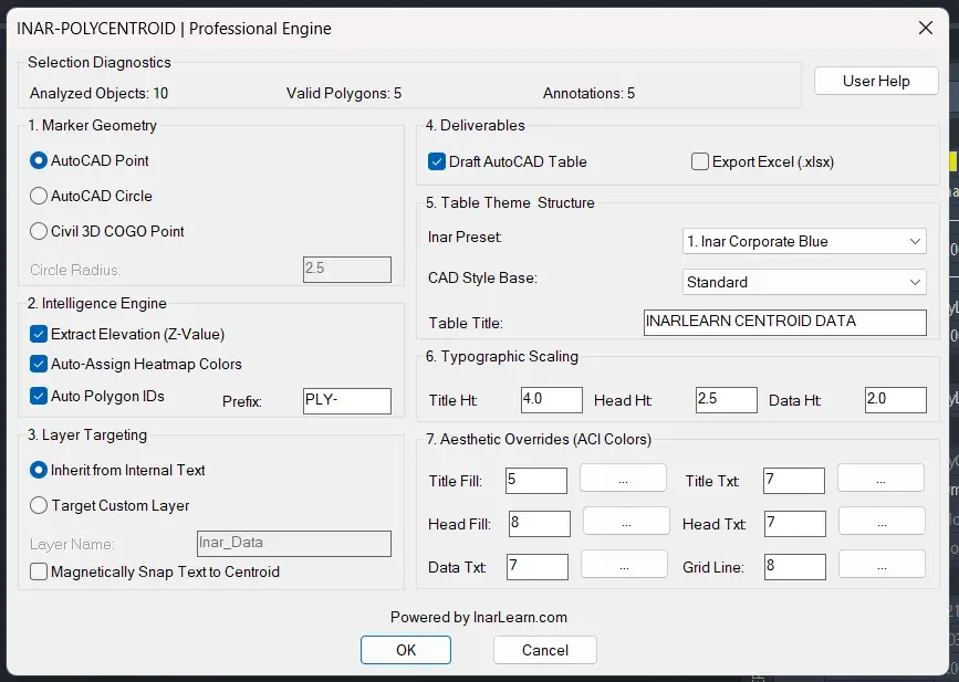
Panel by panel
Marker Geometry
Choose AutoCAD Point, AutoCAD Circle (radius default 2.5 drawing units), or Civil 3D COGO Point. The radius field is only active for the Circle marker type.
Intelligence Engine
Toggle Extract Elevation (Z), Auto-Assign Heatmap Colors for new layers, and Auto Polygon IDs with a custom prefix (default PLY-).
Layer Targeting
Inherit the layer name from the text found inside each polygon, or send everything to one custom layer (default Inar_Data). Optionally snap text to the centroid.
Deliverables
Switch on Draft AutoCAD Table and/or Export Excel (.xlsx). All table controls grey out automatically when the table is switched off.
Table Theme & Structure
Pick one of 10 Inar presets, choose a CAD table style from the current drawing as the structural base, and set the table title.
Typographic Scaling
Set drawing-unit text heights for the title, header, and data rows. Column width, cell margins, and row heights all scale from the data height.
Aesthetic Overrides (ACI colours)
Fine-tune individual colours for title fill, title text, header fill, header text, data text, and grid lines. Click any … button to open AutoCAD’s colour picker.
User Help button
Located in the diagnostics strip. Opens this guide in your default browser so the reference is always one click away from the dialog.
Layer targeting in detail
- Inherit from Internal Text: the routine looks for a text object whose insertion point lies inside the polygon and uses its content as the layer name. No text found means the layer
Inar_Unknown. - Target Custom Layer: every marker goes to the one layer you type.
- Characters that are illegal in layer names (such as
< > / \ : ; ? * | = 'and quotes) are replaced with a dash automatically. - A layer is only created if it does not already exist. New layers receive an automatic colour when the heatmap option is on, otherwise colour 7.
Table Theme Presets
Selecting a preset fills in all three text heights and all six colour fields at once. Colours are AutoCAD Color Index (ACI) numbers. Editing any individual value afterwards automatically switches the preset dropdown to Custom Manual Setup, so you always know whether you are on a stock theme.
Inar Corporate Blue
01Client-facing reports and submissions.
Inar Engineering Dark
02Black-and-white plotting.
Inar Minimalist Clean
03Modern, high-contrast documentation.
Inar High Contrast
04Large-format presentation sheets.
Inar Blueprint Cyan
05Technical and drafting-style deliverables.
Inar Emerald Terrain
06Survey, terrain, and environmental work.
Inar Crimson Alert
07Exception reports and QA reviews.
Inar Monozome (B&W)
08Strict monochrome plot standards.
Inar Royal Magenta
09Marketing and presentation boards.
Inar Warm Amber
10Warm-toned report branding.
Heights are in drawing units. If your drawing is in millimetres or at a large plot scale, increase the three heights so the table is readable when printed. Everything else — column width, cell margins, row heights — scales from the data height.
Understanding the Results
The AutoCAD table and the Excel sheet carry the same six columns, one row per processed polygon. The sample below shows the exact format the routine writes.
| Polygon ID | Easting (X) | Northing (Y) | Elevation (Z) | Area | Layer Zone |
|---|---|---|---|---|---|
| PLY-001 | 5012.347 | 8820.512 | 101.250 | 1250.75 | Plot-A |
| PLY-002 | 5063.918 | 8841.006 | 101.400 | 980.40 | Plot-B |
| PLY-003 | 5098.221 | 8795.774 | 0.000 | 1534.12 | Inar_Unknown |
What each column means
Sequential identifier generated per run, prefixed with your chosen string (default PLY-). Numbering starts at 001 and follows processing order. With IDs off, the column reads N/A.
X coordinate of the computed centroid in drawing units, written with three decimal places. Uses the area-weighted centroid or the concave fallback point where applicable.
Y coordinate of the computed centroid, also to three decimal places. Together with Easting, this defines the exact marker location that was placed in the drawing.
Z value of the polyline’s first vertex, or the polyline’s own elevation if that vertex is at zero. With Extract Elevation off, every value in this column is 0.000.
Enclosed polygon area in raw drawing units squared, reported to two decimal places. In a millimetre drawing the values are square millimetres — convert downstream if you need square metres.
The resolved layer name for that polygon — inherited from the internal text label, or set to your custom target layer. Falls back to Inar_Unknown when no matching text is found.
When the Civil 3D marker type is used, each COGO point receives the polygon ID (or resolved layer name) as its raw description, so the identifier travels with the point through point groups and labels. The Excel export opens with a merged title row, a shaded header row, and auto-fitted columns — the same six fields, laid out identically.
Limitations to Know About
No routine fits every drawing. These are the boundaries of the current engine, grouped by how much they affect your results — so you can decide before you invest time in it.
Hard limits
- Closed polylines only. Open boundaries are counted in the diagnostics but skipped entirely.
- No holes or islands. Only the outer boundary is used; inner rings and voids are ignored.
- Restricted entity types. Hatches, regions, circles, splines, and 3D solids are not accepted in the selection.
- One elevation per polygon. Each result carries a single Z value, not a surface or a range.
Approximations
- Arcs are chords. Bulged segments are measured between vertices, so areas and centroids on arc-heavy boundaries are approximate rather than exact.
- Concave fallback is a scan. The relocated marker is guaranteed to be inside the shape, but it is the nearest grid point — not the mathematical centroid.
- Area is raw units. No unit conversion is applied. Millimetre drawings produce very large numbers.
Environment & workflow
- Windows AutoCAD with COM. Not for AutoCAD LT or AutoCAD for Mac.
- Optional features need optional hosts. Excel export needs desktop Excel; COGO points need Civil 3D.
- Text matching uses insertion points. A label whose insertion point sits outside the boundary will not be picked up.
- ACI colours only. Colours are AutoCAD Color Index values from 1 to 255, not true colour.
- Large selections run slower. Each polygon is checked against every text object in the selection.
How the concave fallback works
For a concave polygon — an L-shape, a crescent, a notched parcel — the mathematical centroid can lie outside the boundary. When that happens the routine tests a 19 × 19 grid of points across the polygon’s bounding box and places the marker at the interior point closest to the true centroid. The result is guaranteed to be inside the shape, but it is an approximation rather than the exact centroid, so check these cases visually.
For legal, survey, or construction deliverables, spot-check a few polygons against AREA or MASSPROP before issuing the data. The routine is designed to be correct and consistent, but a manual verification on a sample is a good habit to keep.
Troubleshooting
Most problems fall into four buckets: the file will not load, the selection is wrong, the output is wrong, or the environment is missing something. Find your symptom below.
Loading the routine 2 issues
Unknown command “INAR-POLYCENTROID”
The file has not been loaded in the current session.
Run APPLOAD and load the file, or add it to the Startup Suite so it loads automatically in future sessions.
File will not load
Security settings are blocking the folder, or the file extension is wrong.
Add the folder to TRUSTEDPATHS, confirm the file is saved as .lsp (not .lsp.txt), or ask your CAD administrator to approve the path.
Selection & geometry 2 issues
“No valid geometry selected”
The selection was empty, or it contained only entity types the routine does not accept.
Select polylines and/or text. Blocks, hatches, splines, and 3D polylines are ignored — select the underlying polyline geometry instead.
“No closed polylines detected”
Every selected polyline is technically open, even if it visually appears closed.
Run PEDIT, select each polyline, and choose Close. Or set the polyline’s Closed property. Rerun and confirm the diagnostics bar shows a non-zero polygon count.
Output & results 3 issues
“Dashboard failed to load”
The temporary DCL file could not be created or read by AutoCAD.
Check that your Windows temp folder is writable and that the disk is not full, then run the command again.
Markers are not visible in the drawing
AutoCAD’s default point style renders as a tiny dot that is easy to miss.
Run DDPTYPE and choose a larger marker — or set PDMODE to 34 and PDSIZE to a suitable value for your drawing scale.
Polygons ended up on layer “Inar_Unknown”
No text insertion point was found inside those polygons, so layer inheritance fell back to the default.
Move the label so its insertion point clearly sits inside the boundary, include it in the selection, and rerun. With MTEXT, check the attachment point.
Environment & external tools 2 issues
“Civil 3D COM API not found”
The routine is running in plain AutoCAD, or in a Civil 3D version whose COM interface it did not recognise.
Nothing is broken — the routine automatically falls back to AutoCAD Points so the run still completes. Switch to Point or Circle if you prefer not to see the alert.
“Excel COM Object could not be instantiated”
Microsoft Excel is missing, blocked by policy, or a macro-security setting is preventing automation.
Install or repair desktop Excel, or leave the Excel toggle off. The AutoCAD table is still produced regardless — the drawing-side deliverable is unaffected.
Best Practices
Eight habits that turn a working tool into a reliable part of your daily CAD workflow. None of them take more than a minute; all of them save time on large datasets.
Save or back up first
Run the engine on a duplicate the first time you use it on a new drawing. Layers and entities are real, permanent changes — even if a single undo reverses them.
Close every boundary
Any polyline that is not flagged as closed will be silently skipped. Run PEDIT → Close before selecting, and confirm the diagnostics count matches your expectation.
One label per polygon
Place exactly one text or mtext object inside each boundary, with its insertion point clearly within the shape. Only the first match is used for the layer name.
Keep label text simple
Avoid heavy MTEXT formatting. Paragraph breaks and symbol characters are replaced with dashes when they become layer names, which can look messy.
Select only what you need
Window-select just the polylines and labels for the current job. A clean selection keeps the run fast and the diagnostics bar readable.
Trial on three or four shapes
Before running the full set, test your chosen theme, layer mode, and marker type on a handful of polygons. Adjust once, then process everything.
Inspect concave shapes
For L-shapes, crescents, and notched boundaries, glance at the placed markers and confirm they sit where you expect inside the polygon.
Keep a shared standard copy
Store the .lsp file in one shared location and load it from every workstation, so the whole team uses the same version and the same defaults.
For drawings with several hundred complex concave polygons, run the engine in groups — one selection per layer or per parcel block. Each batch stays fast and it is much easier to verify the output.
Frequently Asked Questions
What is the command name?
Type INAR-POLYCENTROID at the command line after loading the file.
Does it work with open polylines?
No. A centroid and area only make sense for a closed boundary, so open polylines are counted in the diagnostics but skipped. Close them first with PEDIT.
Do I need Civil 3D or Excel?
No. Both are optional. Without Civil 3D use AutoCAD Points or Circles; without Excel, use the AutoCAD table.
Will it change my original polylines?
No. It adds markers, layers, and a table. The only existing objects it can modify are text objects, and only if you switch on Snap Text to Centroid, which moves the text and places it on the target layer.
Can I undo a run?
Yes. The routine groups its work into one undo step, so a single U reverses it. Anything written to Excel is outside AutoCAD, so close that workbook separately.
How is the area measured?
From the polygon’s vertices, in your drawing units, shown to 2 decimals. If your drawing is in millimetres, the area is in square millimetres; convert in Excel if you need another unit.
Why did a marker land somewhere other than the exact centre?
For concave polygons the true centroid can fall outside the shape. The routine then moves the marker to the nearest interior point it finds, so the marker always sits within the boundary.
Can I change the table colours?
Yes. Pick a preset, or type ACI numbers directly, or click the … button beside any colour box to use the AutoCAD colour picker.
Is it safe to run a LISP file?
A LISP file runs with the same permissions as AutoCAD, so only load files from sources you trust. The file is plain text, so you or your IT team can read it before using it.
Key Takeaways
- INAR-POLYCENTROID calculates the centroid and area of many closed polygons in one run.
- It marks each centroid, assigns an ID and a layer, and delivers an AutoCAD table and optional Excel export.
- Load it with
APPLOAD, then runINAR-POLYCENTROID. - It needs Windows AutoCAD; Civil 3D and Excel are optional extras.
- Boundaries must be closed, and arcs, holes, and concave centroids are approximated.
- Everything is reversible with a single undo.
Need More Help?
Learn more CAD automation
Explore more tutorials, LISP routines, and step-by-step guides at InarLearn.com.
Visit Inar Learn
 Inar Learn